
When dealing with LiDAR we commonly refer to points, returns, pulses or waveforms. But what does the returning signal represent? What are you actually measuring? A step towards further understanding is to actually know how the signal looks like and what objects are going to be hit by the emitted pulse.
Emitting the LiDAR signal
The first thing to be aware of is that the signal disperses the further it gets away from the emitter. The way it progresses towards the signal is therefore cone-shaped and not cylindrical. The rate at which the beam is spread is defined through the system-specific beam divergence angle. Sensor optics with a larger divergence angle increase the signal diameter at a faster rate than sensors with a low divergence angle. The emitted signal pulse will have a non-uniform energy distribution over the surface it covers. Commonly approximated by a two-dimensional Gaussian distribution, the emitted signal has its highest power levels in the center of the beam.
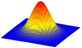
Example of a two-dimensional Gauss distribution
Looking at this example of a two-dimensional Gauss – where would you define the width of the LiDAR signal? The nature of the Gauss distribution makes this very difficult. The simplest way of defining the width of a beam is to choose two diametrically opposite points on this surface. This could geometrically be described as cutting this peak with a surface parallel to the 0-level. This results in a circle of which the diameter can be determined. There is different levels at which this intersection is normally done:
- FWHM (Full width at half maximum): The peak is cut half way between the top and the base. This way all points on the resulting circle will have a power intensity which is 50% of the peak.
- 1/e² width: The peak is cut where the power is at 1/e² which equals to 0.135 times the maximum in the center of the beam. This definition is frequently used because the 2-dimensional Gaussian distribution allows to easily calculate the diameter at this level.
- 1/e width: The diameter is calculated at 1/e, respectively where the signal is at 36.8% of its maximum. This definition is used for computing the maximum permissible exposure to a laser beam when looking at the safety aspect of LiDAR signals.
An important thing to be aware of is that the total amount of pulse energy remains the same regardless of the beam divergence the sensor optics produces. As a result sensors with a larger beam divergence will spread the pulse energy over a larger area which leads to a lower signal-to-noise ratio. This can make it more difficult in certain circumstances to distinguish the returning signal from general noise in the data.
Impact of flight altitude
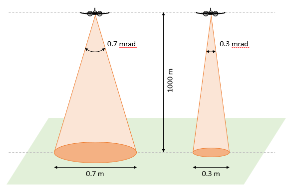 Knowing now that the signal spreads with distance it becomes clear that the higher a survey aircraft flies the larger the resulting signal footprint on the ground will be. The beam divergence is normally given in mrad, which makes it easy to calculate the footprint diameter at a given flying altitude.
Combining footprint diameter with the correct pulse spacing
As Martin Isenburg pointed out in his comment to this article below, LiDAR footprint diameter have to be considered also in respect to the point spacing of your LiDAR data.
In order to achieve a full coverage of the area, point spacing should be equal to the footprint diameter. In a perfect scenario these footprint discs will then line up nicely and be similar to the 2-dimensional coverage grid we know from aerial photography.
With a point spacing smaller than the footprint diameter, LiDAR signals will overlap and certain areas and/or objects can then trigger returns in multiple LiDAR beams. Spacing LiDAR signals at larger intervals will lead to areas between the footprints not being mapped.
Importance of the LiDAR footprint
Now that you know what factors contribute to the resulting factor – why would you care? Thinking about your project it is definitely important to understand the final result that you are aiming for. Depending on your mission, being aware of the size of your LiDAR footprint will help determine the required specifications and parameters.
A large LiDAR footprint can be beneficial if we want to be sure to detect small or thin objects like for example power lines. A larger illuminated area will also help to ensure that some part of the signal penetrates the forest canopy.
On the other hand, a small LiDAR footprint will result in a more distinctive return. With a smaller illuminated area the signal is also more likely to be returned from a single homogeneous surface and as a result multiple returns will be less likely.
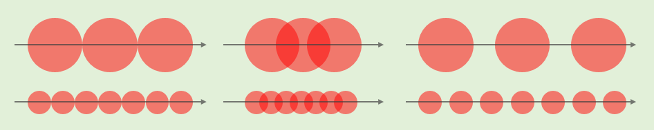
The image above shows examples of pulse spacing equal to footprint diameter (left), shorter than footprint diameter (center) and larger than the footprint diameter (right).
While end-customer will spend some consideration on the best suitable footprint size, data provider will have to figure out which sensor to use (determines the beam divergence angle) and at which flying altitude to collect the data. How much consideration do you spend on the diameter size of your LiDAR footprint?
To be complete, I think the article should also include a discussion on the most important consideration when deciding about what “footprint size to fly at” … and that is the pulse spacing on the ground. For larger pulse spacings we will typically want larger footprint sizes to avoid the aliasing artifacts of sampling the “high-frequency terrain” with a probe able to record tiniest details. A large footprint will in a way perform the required “down-sampling” of the terrain that gets my sampling more in line with the Nyquist theorem …
You are completely correct Martin. I added a section trying to explain this relation between footprint diameter and pulse spacing.
From tenders I have seen it now often that a certain footprint diameter is given by the customer. As a result this should then be considered when preparing the flight plans and its parameters…
I am confused on something does the lidar lite when used on motors rather than drones will the point spacing and diameter have to be equal?? As I don’t know exactly how to fix this in my code.